Metallic HCF BISON Model: 3D cycle fuel performance
Contact: Youyeon Choi (MIT), yychoi@mit.edu
This model also includes contributions by Guillaume Giudicelli (INL), Daniel Levario (UNM), Kyle Gamble (INL) and Koroush Shirvan (MIT)
Model link: Metallic HCF BISON Model
High Level Summary of Model
This model aims to simulate a cycle fuel performance of Helical Cruciform Fuel (HCF) under water-cooled Small Modular Reactor (SMR) conditions using BISON. As shown in Figure 1, HCF design is composed of three different regions: the central displacer, fuel and cladding. From a materials perspective, the fuel material is U-50 wt.% Zr (U-50Zr) alloy, whose primary phase is -UZr, which is different from conventional U-rich metallic fuels used in fast reactor applications. A Zr-based M5 alloy is used for the cladding, and the displacer region is expected to be filled with pure Zr or burnable absorber for neutronic core design.
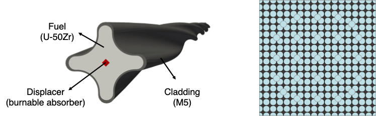
Figure 1: HCF geometry and 17x17 lattice configuration.
Computational Model Description
Files used by this model include:
moose_hcf_mesher.i: input for MOOSE to generate a single 3D rod HCF meshinput.i: main input for BISON for the fuel performance simulationA CSV (comma-separated value) file defining the linear (axial) heat generation rate of the fuel
CSV files defining the material properties (thermal conductivity, specific heat capcity, and thermal expansion) of U-50Zr fuel
This document describes a few elements specific to the input file of this model (input.i).
Input Files description
Mesh
moose_hcf_mesher.i is used to generate a HCF mesh with first-order hexahedral elements (HEX8) for BISON simulation. The geometry can be split into several curves, made of 1D edge elements, and those can be represented with an explicit (parameterized) formulations, which can be created by MOOSE using the ParsedCurveGenerator. After that, those curves are stitched to form an enclosed boundary using StitchMeshGenerator and the 2D mesh is generated by filling with 2D elements between the two curves using the FillBetweenCurvesGenerator. To extrude the mesh with an axial twist, the AdvancedExtruderGenerator is used with the twist_pitch parameter. Finally, to generate the sidesets and nodesets which are being used to apply boundary conditions, BoundingBoxNodeSetGenerator, SideSetsFromNormalsGenerator and ParsedGenerateSideset are used for various surfaces. The user can control the mesh density through several parameters defined at the top of the input file, such as n_seg_lobe, n_seg_valley, n_seg_l2v, n_center, n_fuel_radial, n_clad_radial, and n_per_axial_pitch. Furthermore, detailed geometrical specifictions can be controlled through addtional input file parameters such as r_fuel, r_clad, R_fuel, R_clad, c_lobe_clad, c_lobe_valley, and c_valley. Figure 2 shows the definition of geometric parameters and Table 1 summarizes the geometric parameters used in mesh generator and specific values used in this model.
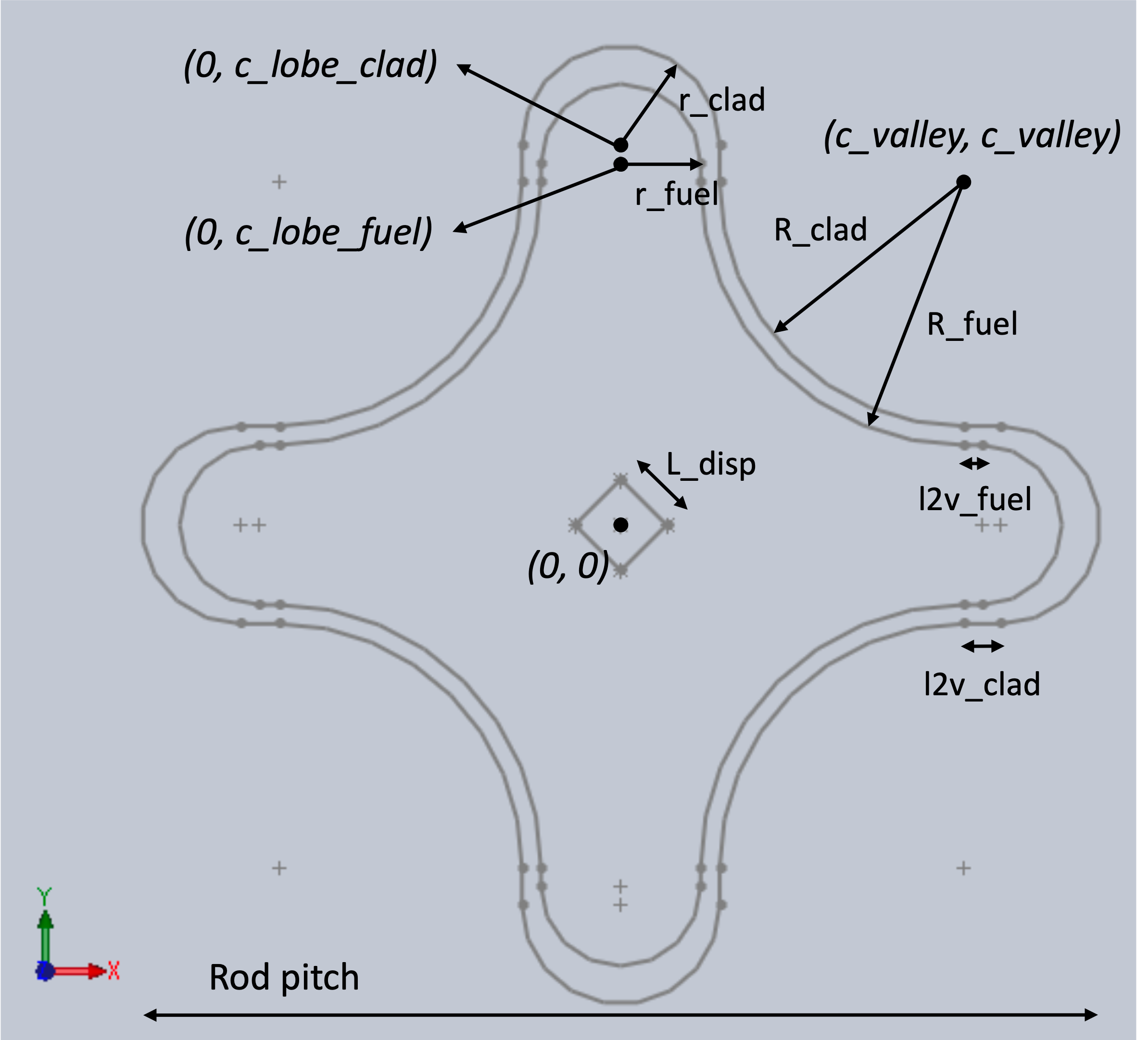
Figure 2: Definition of geometric parameters of HCF.
Table 1: Geometric specifications of HCF (see figure for parameter meaning).
| Parameter | Value (mm) |
|---|---|
| r_fuel | 1.05 |
| r_clad | 1.30 |
| R_fuel | 3.45 |
| R_clad | 3.20 |
| l2v_fuel | 0.25 |
| l2v_clad | 0.50 |
| c_lobe_clad | 5.00 |
| c_lobe_fuel | 4.75 |
| c_valley | 4.50 |
| L_disp | 0.85 |
| Rod pitch | 12.6 |
| Axial pitch | 500 |
Any MOOSE applicaton can be used to generate a HCF mesh using this input as all the objects used are part of the core MOOSE framework. For instance, a BISON user may execute the following command on any of INL's HPC Cluster:
module load use.moose bison-openmpi
bison-opt -i moose_hcf_mesher.i
This will generate the HCF mesh file (mesh.e), which is used in BISON simulations.
Functions
BISON is capable of modeling U-Pu-Zr alloy fuel for fuel performance analysis. However, the metallic fuel models in BISON are based on the experimental data for fast reactor applications where the fuels were U-rich alloys, which are mostly in -phase with less than approximately 10 wt.\% of Zirconium content. Given that U-50Zr alloy will operate in a different phase (-phase), there is a high uncertainty in using existing models for this application.
To reduce uncertainties associated with applying models for different phases, the material properties are implemented through Functions to better represent the characteristics of the U-50Zr alloy, using published studies of U-Zr alloys. Specifically, thermal properties including thermal conductivity, heat capacity, and thermal expansion are implemented based on experimental data from Idaho National Laboratory (INL) (Beausoleil et al., 2021), where a preliminary thermophysical and mechanical evaluation of unirradiated U-50Zr was conducted. INL's experimental data exhibit good agreement with previously reported measurements for U-50Zr, whereas BISON's models, which are specifically developed for U-rich U-Zr alloys, show noticeable discrepancies. This highlights the importance of applying phase-appropriate thermal properties to ensure accurate fuel performance analysis.
[Functions]
  [u50zr_thermal_conductivity]
    type = PiecewiseLinear
    data_file = U50Zr_thermal_conductivity.csv ## Temperature [K] vs. thermal conductivity (W/m-K)from INL report
    format = columns
  []
[]
[Functions]
  [u50zr_heat_capacity]
    type = PiecewiseLinear
    data_file = U50Zr_heat_capacity.csv ## Temperature [K] vs. heat capacity (J/kg-K) from INL report
    format = columns
  []
[]
[Functions]
  [u50zr_therm_expan]
    type = PiecewiseLinear
    data_file = U50Zr_thermal_expansion.csv ## Temperature [K] vs. thermal expansionfrom INL report
    format = columns
  []
[]
CoolantChannel BISON syntax
This model uses normal operating conditions of the 250 MWth NuScale Power Module (NPM). Figure 3 shows the linear heat generation rate (LHGR) history of the hot fuel pin obtained from a NPM replica design developed at the Massachusetts Institute of Technology (MIT) (Halimi and Shirvan, 2025). The pin-wise peak LHGR is used in this model to simulate the most limiting condition. Table 2 summarizes the thermal-hydraulic parameters used in BISON through the CoolantChannel action. The flow area corresponds to the subchannel area with a rod pitch of 1.26 cm. The heated diameter is the cylinder-equivalent diameter of the HCF rod, and the heated perimeter is the perimeter of the outer fuel surface. Lastly, the hydraulic diameter is computed using Eq. (1). Note that additional turbulent mixing from the helical fuel shape is not taken into account in the 1D axial coolant model.
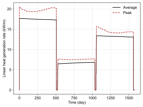
Figure 3: Linear heat generation rate history of the hot fuel.
Table 2: Thermal-hydraulic parameters for HCF used in BISON.
| Parameter | Unit | Value |
|---|---|---|
| Inlet temperature | 522 | |
| Inlet pressure | 13.8 | |
| Inlet mass flux | 771 | |
| Flow area | 94.11 | |
| Heated diameter | mm | 9.97 |
| Heated perimeter | mm | 40.44 |
| Hydraulic diameter | mm | 9.31 |
(1)
Materials
(Ahn et al., 2016) reported that orders-of-magnitude differences in the size of gas bubbles between the U-0.1Zr alloy (-U phase) and U-40Zr alloy (-UZr phase) following 140 keV He ion irradiation. In the irradiated U-40Zr alloy, the average bubble diameter was approximately 6nm and remained nearly constant across different irradiation doses. To capture this phase-dependent bubble size effect, the fuel volumetric swelling model in BISON (UPuZrVolumetricSwellingEigentrain) was modified by incorporating the fission gas bubble radius as an input parameter (bubble_radius). In this model, the bubble radius is fixed at 10 nm, which is about twice the reported size, as a conservative assumption. This assumption should be revisited once experimental data on volumetric swelling under neutron irradiation become available. Lastly, it is worth noting that zirconium redistribution in the fuel, which could affect the thermal properties and radial fission rate distribution in the fuel, is not yet considered in this model due to the lack of validation of existing models for three-dimensional case.
[Materials]
  [fuel_swelling]
    type = UPuZrVolumetricSwellingEigenstrain
    eigenstrain_name = 'fuel_swelling_strain'
    block = 'fuel'
    burnup = burnup
    hydrostatic_stress = hydrostatic_stress
    fission_rate = fission_rate
    initial_porosity = 0.1
    bubble_radius = 10e-9 # new input paramter for fission gas bubble radius
  []
[]
Running the model
The user can run BISON in parallel on INL's HPC Cluster with the command below:
module load use.moose bison-openmpi
mpiexec -n 48 bison-opt -i input.i
References
- Sangjoon Ahn, Sandeep Irukuvarghula, and Sean M. McDeavitt.
Microstructure of α-U and δ-UZr2 phase uranium–zirconium alloys irradiated with 140-keV He+ ion-beam.
Journal of Alloys and Compounds, 681:6–11, October 2016.
doi:10.1016/j.jallcom.2016.04.219.[Export]
BibTeX
@article{ahn_microstructure_2016,
    author = "Ahn, Sangjoon and Irukuvarghula, Sandeep and McDeavitt, Sean M.",
    title = "Microstructure of $\alpha$-{U} and $\delta$-{UZr2} phase uranium–zirconium alloys irradiated with 140-{keV} {He}+ ion-beam",
    volume = "681",
    issn = "09258388",
    doi = "10.1016/j.jallcom.2016.04.219",
    abstract = "Ion-beam irradiation has been conducted to demonstrate and assess solid phase dependence of fission gas bubble nucleation and growth in metallic nuclear fuels. Differential formation and growth of irradiation-induced voids and bubbles were observed from as-cast uranium-zirconium (UeZr) alloys including 0.1 and 40 wt\\% zirconium. The UeZr alloys were irradiated with 140-keV Heþ ions with fluences ranged from 1 Â 1014 ions/cm2 to 5 Â 1016 ions/cm2. Several larger spherical bubbles ({\textless}{\textasciitilde}70 nm) were revealed from an irradiated single a-U phase alloy (Ue0.1Zr) in which observed bubbles were mobile under 200-keV electron beam of transmission electron microscope (TEM). In-situ mergence and leakage of the bubbles in the uranium-rich alloy was also evident during the observation. In contrast, numerous number of small ({\textasciitilde}6 nm) angular voids, or low pressure bubbles, were found in an irradiated d-UZr2 phase alloy (Ue40Zr), in which the radiation-induced nanostructure was stationary throughout the observation. This study may reaffirm higher radiation-susceptibility of the a-U phase than the d-UZr2 phase, which could strengthen the needs of separate accounting of solid phase effects for metallic fuel performance modeling particularly regarding the fuel restructuring phenomena, such as fission gas swelling and constituent redistribution, since conventional models are commonly adopted homogeneous medium assumption, not in accordance with the results of post-irradiation examinations of used metallic nuclear fuel in which the formation of several concentric phase zone was distinct corresponding to a steep radial temperature gradient in the fuel pin and multiple isotherm lines in the binary phase diagram of UeZr alloy system.",
    language = "en",
    urldate = "2024-03-28",
    journal = "Journal of Alloys and Compounds",
    month = "October",
    year = "2016",
    pages = "6--11"
}
RIS
TY  - JOUR
AU  - Ahn, Sangjoon
AU  - Irukuvarghula, Sandeep
AU  - McDeavitt, Sean M.
TI  - Microstructure of α-U and δ-UZr2 phase uranium–zirconium alloys irradiated with 140-keV He+ ion-beam
JO  - Journal of Alloys and Compounds
PY  - 2016
VL  - 681
DO  - 10.1016/j.jallcom.2016.04.219
SP  - 6
EP  - 11
ER  -
Plain Text
Sangjoon Ahn, Sandeep Irukuvarghula, and Sean M. McDeavitt. Microstructure of α-U and δ-UZr2 phase uranium–zirconium alloys irradiated with 140-keV He+ ion-beam. Journal of Alloys and Compounds, 681:6–11, October 2016. doi:10.1016/j.jallcom.2016.04.219. - Geoffrey Beausoleil, Mahmut Cinbiz, Tiankai Yao, Yachun Wang, Fidelma Di Lemma, Cynthia Adkins, Tsvetoslav Pavlov, Rongjie Song, Luca Capriotti, and Walter Williams.
U-50Zr Microstructure and Property Assessment for LWR Applications.
Technical Report INL/EXT21-64614, 1825221, Idaho National Laboratory, Idaho Falls, Idaho, September 2021.
doi:10.2172/1825221.[Export]
BibTeX
@techreport{beausoleil_u-50zr_2021,
    author = "Beausoleil, Geoffrey and Cinbiz, Mahmut and Yao, Tiankai and Wang, Yachun and Di Lemma, Fidelma and Adkins, Cynthia and Pavlov, Tsvetoslav and Song, Rongjie and Capriotti, Luca and Williams, Walter",
    address = "Idaho Falls, Idaho",
    title = "U-{50Zr} {Microstructure} and {Property} {Assessment} for {LWR} {Applications}",
    language = "en",
    number = "INL/EXT21-64614, 1825221",
    urldate = "2023-12-20",
    institution = "Idaho National Laboratory",
    month = "September",
    year = "2021",
    doi = "10.2172/1825221"
}
RIS
TY  - RPRT
AU  - Beausoleil, Geoffrey
AU  - Cinbiz, Mahmut
AU  - Yao, Tiankai
AU  - Wang, Yachun
AU  - Di Lemma, Fidelma
AU  - Adkins, Cynthia
AU  - Pavlov, Tsvetoslav
AU  - Song, Rongjie
AU  - Capriotti, Luca
AU  - Williams, Walter
TI  - U-50Zr Microstructure and Property Assessment for LWR Applications
PY  - 2021
IS  - INL/EXT21-64614, 1825221
CY  - Idaho Falls, Idaho
DO  - 10.2172/1825221
ER  -
Plain Text
Geoffrey Beausoleil, Mahmut Cinbiz, Tiankai Yao, Yachun Wang, Fidelma Di Lemma, Cynthia Adkins, Tsvetoslav Pavlov, Rongjie Song, Luca Capriotti, and Walter Williams. U-50Zr Microstructure and Property Assessment for LWR Applications. Technical Report INL/EXT21-64614, 1825221, Idaho National Laboratory, Idaho Falls, Idaho, September 2021. doi:10.2172/1825221. - Assil Halimi and Koroush Shirvan.
Fuel Behavior Implications of Reactor Design Choices in Pressurized Water SMRs.
Nuclear Technology, 211(8):1723–1746, August 2025.
doi:10.1080/00295450.2024.2426416.[Export]
BibTeX
@article{halimi_fuel_2025,
    author = "Halimi, Assil and Shirvan, Koroush",
    title = "Fuel {Behavior} {Implications} of {Reactor} {Design} {Choices} in {Pressurized} {Water} {SMRs}",
    volume = "211",
    issn = "0029-5450, 1943-7471",
    doi = "10.1080/00295450.2024.2426416",
    abstract = "Small pressurized water reactors can feature boron-free operation, natural circulation mode, reduced-height assemblies, and/or long refueling cycles. This paper attempts to explore core design optimization for each of these design evolutions. In consequence, five core design layouts are developed incorporating boron-free operation with continuous control rod insertion, natural circulation with low burnup/low power density design, natural circulation with high burnup/low power density design, forced circulation with standard core power density design, and forced circulation with high power density design. These cores’ performance is compared to a standard four-loop pressurized water reactor. The design process aims to improve the fuel cycle cost under safety constraints through core design optimization using the CASMO4E/SIMULATE3 reactor physics codes and the FRAPCON4.1 fuel performance assessment tool. Core modeling assumes standard 17×17 PWR fuel assemblies loaded with low enriched uranium up to 5 wt\\% or low enriched uranium plus (i.e. below 10 wt\\% enrichment) pellets with gadolinium oxide as the burnable poison. Satisfactory core and fuel performances are obtained for all the designed cores under steady state and considered overpower transients. For low power density operation, long cycle lengths are achieved reaching 2.5-year and 5-year cycles, and peak rod-average burnup is pushed to 83 MWd/kgU. Other cycle lengths are maintained at 18 months. Boron-free operation exhibits the ability to achieve longer cycle lengths at the cost of higher peaking factors leading to high local power and fuel temperatures, which prevents sizable power uprates and is deemed uneconomical. Fuel assembly height reduction allows coolant velocity retrofit, which enables higher core power density without violating the structural integrity of the fuel assembly. As a result, a core power density of 123 kW/L is reached where total cladding hoop strain becomes the limiting parameter.",
    language = "en",
    number = "8",
    urldate = "2025-11-19",
    journal = "Nuclear Technology",
    month = "August",
    year = "2025",
    pages = "1723--1746"
}
RIS
TY  - JOUR
AU  - Halimi, Assil
AU  - Shirvan, Koroush
TI  - Fuel Behavior Implications of Reactor Design Choices in Pressurized Water SMRs
JO  - Nuclear Technology
PY  - 2025
VL  - 211
IS  - 8
DO  - 10.1080/00295450.2024.2426416
SP  - 1723
EP  - 1746
ER  -
Plain Text
Assil Halimi and Koroush Shirvan. Fuel Behavior Implications of Reactor Design Choices in Pressurized Water SMRs. Nuclear Technology, 211(8):1723–1746, August 2025. doi:10.1080/00295450.2024.2426416.
(lwr/hcf/input.i)
[GlobalParams]
  displacements = 'disp_x disp_y disp_z'
  temperature = temp
  X_Zr = 0.7229  # U-50Zr
  X_Pu = 0.0
  order = FIRST
  family = LAGRANGE
  volumetric_locking_correction = true
[]

###################################################################################################

[Problem]
  type = ReferenceResidualProblem
  reference_vector = 'ref'
  extra_tag_vectors = 'ref'
  converge_on = 'disp_x disp_y disp_z temp'
[]

###################################################################################################

[Mesh]
  # Import mesh file
  [mesh]
    type = FileMeshGenerator
    file = 'mesh.e'
  []
  centroid_partitioner_direction = y
[]

###################################################################################################

[Variables]
  [temp]
    initial_condition = 522.0
  []
[]

###################################################################################################

[AuxVariables]
  [fast_neutron_flux]
    block = 'cladding'
  []
  [fast_neutron_fluence]
    block = 'cladding'
  []
  [solid_swell]
    block = 'fuel'
    order = CONSTANT
    family = MONOMIAL
  []
  [gas_swell]
    block = 'fuel'
    order = CONSTANT
    family = MONOMIAL
  []
  [total_hoop_strain]
    block = 'cladding'
    order = CONSTANT
    family = MONOMIAL
  []
  [creeprate]
    order = CONSTANT
    family = MONOMIAL
  []
  [primary_creep]
    order = CONSTANT
    family = MONOMIAL
  []
  [thermal_secondary_creep]
    block = 'cladding displacer'
    order = CONSTANT
    family = MONOMIAL
  []
  [thermal_creep]
    block = 'fuel'
    order = CONSTANT
    family = MONOMIAL
  []
  [irradiation_creep]
    order = CONSTANT
    family = MONOMIAL
  []
  [oxide_thickness] # ZrO2 scale thickness (m)
    block = 'cladding'
    order = CONSTANT
    family = MONOMIAL
  []
[]

###################################################################################################

[Functions]
  [power_history]
    type = PiecewiseLinear
    data_file = lhgr_peak.csv   # time vs. linear power
    format = columns
  []
  [axial_peaking_factors]
    type = ConstantFunction
    value = 1.0
  []
  [fission_rate_scale_factor]
    type = ParsedFunction
    expression = 6.019803e14 # 1/cross_sectional_area_of_fuel/energy_per_fission
  []
  [fission_history]
    type = CompositeFunction
    functions = 'power_history fission_rate_scale_factor'
  []
  [u50zr_thermal_conductivity]
    type = PiecewiseLinear
    data_file = U50Zr_thermal_conductivity.csv ## Temperature [K] vs. thermal conductivity (W/m-K)from INL report
    format = columns
  []
  [u50zr_heat_capacity]
    type = PiecewiseLinear
    data_file = U50Zr_heat_capacity.csv        ## Temperature [K] vs. heat capacity (J/kg-K) from INL report
    format = columns
  []
  [u50zr_therm_expan]
    type = PiecewiseLinear
    data_file = U50Zr_thermal_expansion.csv    ## Temperature [K] vs. thermal expansionfrom INL report
    format = columns
  []
[]

###################################################################################################

[Physics/SolidMechanics/QuasiStatic]
  strain = FINITE
  add_variables = true
  generate_output = 'vonmises_stress hydrostatic_stress hoop_stress stress_xx stress_yy stress_zz strain_xx strain_yy strain_zz elastic_strain_xx elastic_strain_yy elastic_strain_zz
                     creep_strain_xx creep_strain_yy creep_strain_zz hoop_strain hoop_creep_strain hoop_elastic_strain'
  [fuel]
    block = fuel
    eigenstrain_names = 'fuel_thermalexp_strain fuel_swelling_strain'
    additional_generate_output = 'volumetric_strain'
    decomposition_method = EigenSolution
  []
  [cladding]
    block = cladding
    eigenstrain_names = 'clad_thermalexp_strain clad_irrad_strain'
    extra_vector_tags = 'ref'
    additional_generate_output = 'plastic_strain_xx plastic_strain_yy plastic_strain_zz hoop_plastic_strain'
    decomposition_method = EigenSolution
  []
  [displacer]
    block = displacer
    eigenstrain_names = 'disp_thermalexp_strain'
    extra_vector_tags = 'ref'
    decomposition_method = EigenSolution
  []
[]

###################################################################################################

[Kernels]
  [gravity]
    type = Gravity
    variable = disp_y
    value = -9.81
    extra_vector_tags = 'ref'
  []
  [heat]
    type = HeatConduction
    variable = temp
    extra_vector_tags = 'ref'
  []
  [heat_ie]
    type = HeatConductionTimeDerivative
    variable = temp
    extra_vector_tags = 'ref'
  []
  [heat_source]
    type = FissionRateHeatSource
    block = fuel
    variable = temp
    fission_rate = 'fission_rate'
    extra_vector_tags = 'ref'
  []
[]

###################################################################################################

[AuxKernels]
  [fast_neutron_flux]
    type = FastNeutronFluxAux
    variable = fast_neutron_flux
    block = cladding
    factor = 3e13
    rod_ave_lin_pow = power_history
    axial_power_profile = axial_peaking_factors
    execute_on = timestep_begin
  []
  [fast_neutron_fluence]
    type = FastNeutronFluenceAux
    variable = fast_neutron_fluence
    block = cladding
    fast_neutron_flux = fast_neutron_flux
    execute_on = timestep_begin
  []
  [gas_swell]
    type = MaterialRealAux
    variable = gas_swell
    block = fuel
    property = gas_swelling
    execute_on = timestep_end
  []
  [solid_swell]
    type = MaterialRealAux
    variable = solid_swell
    block = fuel
    property = solid_swelling
    execute_on = timestep_end
  []
  [total_hoop_strain]
    type = RankTwoAux
    rank_two_tensor = total_strain
    variable = total_hoop_strain
    index_j = 2
    index_i = 2
    execute_on = timestep_end
  []
  [creeprate]
    type = MaterialRealAux
    property = creep_rate
    execute_on = timestep_end
    variable = creeprate
  []
  [primary_creep]
    type = MaterialRealAux
    block = cladding
    property = primary_creep_strain
    execute_on = timestep_end
    variable = primary_creep
  []
  [thermal_secondary_creep]
    type = MaterialRealAux
    block = cladding
    property = thermal_secondary_creep_strain
    execute_on = timestep_end
    variable = thermal_secondary_creep
  []
  [thermal_creep]
    type = MaterialRealAux
    block = fuel
    property = thermal_creep_strain
    execute_on = timestep_end
    variable = thermal_creep
  []
  [irradiation_creep]
    type = MaterialRealAux
    block = 'fuel cladding'
    property = irradiation_creep_strain
    execute_on = timestep_end
    variable = irradiation_creep
  []
  [oxide_thickness]
    type = MaterialRealAux
    boundary = 'side'
    variable = oxide_thickness
    property = oxide_scale_thickness
    execute_on = 'linear'
  []
[]

[BCs]
  [no_x_bottom_node]
    type = DirichletBC
    variable = disp_x
    boundary = 'bcenter'
    value = 0.0
  []
  [no_z_bottom_node]
    type = DirichletBC
    variable = disp_z
    boundary = 'bcenter bcenter_nx'
    value = 0.0
  []
  [no_y_bottom_node]
    type = DirichletBC
    variable = disp_y
    boundary = 'bcenter'
    value = 0.0
  []
  [no_y_bottom]
    type = DirichletBC
    variable = disp_y
    boundary = 'bottom'
    value = 0.0
  []
  [Pressure]
    [coolantPressure]
      boundary = side
      factor = 13.8e6
    []
  []
[]

###################################################################################################

[CoolantChannel]
  [convective_clad_surface] # apply convective boundary to clad outer surface
    boundary = side
    variable = temp
    inlet_temperature = 522.0        # K
    inlet_pressure    = 13.8e6       # Pa
    inlet_massflux    = 771          # kg/m^2-sec
    flow_area = 9.4111e-05           # m2
    heated_diameter = 9.0727e-3      # m
    heated_perimeter = 4.0443e-2     # m
    hydraulic_diameter = 9.3082e-3   # m
    linear_heat_rate  = power_history
    axial_power_profile = axial_peaking_factors
    oxide_thickness = oxide_thickness
  []
[]

###################################################################################################

[Materials]
  ## fuel: U-50Zr
  [fission_rate]
    type = GenericFunctionMaterial
    block = 'fuel'
    prop_names = 'fission_rate'
    prop_values = fission_history
    outputs = all
  []
  [burnup]
    type = UPuZrBurnup
    block = 'fuel'
    density = 9640.0
    initial_X_Zr = 0.7229
    initial_X_Pu = 0.0
    fission_rate = fission_rate
  []
 [fuel_thermal]
   type = HeatConductionMaterial
   block = 'fuel'
   thermal_conductivity_temperature_function = u50zr_thermal_conductivity
   specific_heat_temperature_function = u50zr_heat_capacity
   temperature = temp
 []
  [fuel_density]
    type = StrainAdjustedDensity
    block = fuel
    strain_free_density = 9640
  []
  [fuel_elasticity_tensor]
    type = UPuZrElasticityTensor
    temperature = temp
    block = 'fuel'
    youngs_model = LANL
  []
  [fuel_stress]
    type = ComputeMultipleInelasticStress
    block = 'fuel'
    inelastic_models = 'fuel_creep'
    tangent_operator = elastic
  []
  [fuel_creep]
    type = UPuZrCreepUpdate
    block = 'fuel'
  []
  [fuel_swelling]
    type = UPuZrVolumetricSwellingEigenstrain
    eigenstrain_name = 'fuel_swelling_strain'
    block = 'fuel'
    burnup = burnup
    hydrostatic_stress = hydrostatic_stress
    fission_rate = fission_rate
    initial_porosity = 0.1
    bubble_radius = 10e-9 # new input paramter for fission gas bubble radius
  []
  [fuel_thermal_expansion]
    type = ComputeDilatationThermalExpansionFunctionEigenstrain
    block = 'fuel'
    dilatation_function = u50zr_therm_expan
    eigenstrain_name = 'fuel_thermalexp_strain'
    stress_free_temperature = 300
  []
  [fission_gas_release]
    type = UPuZrFissionGasRelease
    block = 'fuel'
    fission_rate = fission_rate
  []
  [fuel_phase]
    type = UPuZrPhase
    block = 'fuel'
    temperature = temp
  []

  ## cladding: Zr-1%Nb (M5)
  [clad_thermal]
    type = ZryThermal
    block = 'cladding'
  []
  [clad_density]
    type = StrainAdjustedDensity
    block = 'cladding'
    strain_free_density = 6551.0
  []
  [clad_thermal_expansion]
    block = 'cladding'
    type = ZryThermalExpansionMATPROEigenstrain
    eigenstrain_name = clad_thermalexp_strain
    stress_free_temperature = 300
    axial_direction = y
  []
  [clad_elasticity_tensor]
    type = ZryElasticityTensor
    block = 'cladding'
    fast_neutron_fluence = fast_neutron_fluence
    matpro_poissons_ratio = true
    matpro_youngs_modulus = true
  []
  [clad_stress]
    type = ComputeMultipleInelasticStress
    block = 'cladding'
    inelastic_models = 'clad_plas clad_creep'
    tangent_operator = elastic
  []
  [clad_plas]
    type = ZryPlasticityUpdate
    block = 'cladding'
    fast_neutron_fluence = fast_neutron_fluence
    fast_neutron_flux = fast_neutron_flux
    plasticity_model_type = MATPRO
  []
  [clad_creep]
    type = ZryCreepLimbackHoppeUpdate
    block = 'cladding'
    temperature = temp
    fast_neutron_fluence = fast_neutron_fluence
    fast_neutron_flux = fast_neutron_flux
    zircaloy_material_type = M5
  []
  [clad_irrad_growth]
    type = ZryIrradiationGrowthEigenstrain
    block = 'cladding'
    eigenstrain_name = clad_irrad_strain
    fast_neutron_fluence = fast_neutron_fluence
    zircaloy_material_type = M5
    axial_direction = 1
  []
  [oxidation_zry]
    type = ZryOxidation
    boundary = side
    clad_inner_radius = 0.004093 # hcf --> cylinder equivalent radius
    clad_outer_radius = 0.004536
    normal_operating_temperature_model = epri_kwu_ce
    high_temperature_model = leistikow
    fast_neutron_flux = fast_neutron_flux
    oxygen_weight_fraction_initial = 0.0
    use_coolant_channel = true
  []

  ## displacer: pure Zirconium
  [disp_thermal]
    type = ZrThermal
    block = 'displacer'
  []
  [disp_density]
    type = StrainAdjustedDensity
    block = 'displacer'
    strain_free_density = 6530.0
  []
  [disp_thermal_expansion]
    type = ZrThermalExpansionEigenstrain
    block = 'displacer'
    stress_free_temperature = 300
    eigenstrain_name = disp_thermalexp_strain
  []
  [disp_elasticity_tensor]
    type = ComputeIsotropicElasticityTensor
    block = 'displacer'
    youngs_modulus = 94.5e9
    poissons_ratio = 0.34
  []
  [disp_stress]
    type = ComputeMultipleInelasticStress
    block = 'displacer'
    tangent_operator = elastic
    inelastic_models = 'disp_zrcreep'
  []
  [disp_zrcreep]
    type = ZrCreepUpdate
    block = 'displacer'
  []
[]

###################################################################################################

[Executioner]
  type = Transient
  solve_type = 'PJFNK'

  petsc_options = '-snes_converged_reason -ksp_converged_reason -snes_ksp_ew'
  petsc_options_iname = '-pc_type -mat_mffd_err -pc_factor_shift_type -pc_factor_shift_amount -pc_factor_mat_solver_package'
  petsc_options_value = 'lu       1e-6          NONZERO               1e-15                   superlu_dist'

  l_max_its = 50
  l_tol = 1e-4
  nl_max_its = 40
  nl_rel_tol = 1e-4
  nl_abs_tol = 1e-8

  start_time = 0
  end_time = 136235520

  dtmax = 2e6
  dtmin = 1

  [TimeStepper]
    type = IterationAdaptiveDT
    dt = 100
    optimal_iterations = 15
    iteration_window = 3
    growth_factor = 2
    cutback_factor = .5
    force_step_every_function_point = true
    timestep_limiting_function = power_history
  []
[]

###################################################################################################

[Postprocessors]
  [_dt]
    type = TimestepSize
  []
  [_nl_its]
    type = NumNonlinearIterations
  []
  [rod_total_power]
    type = ElementIntegralPower
    block = fuel
    fission_rate = fission_rate
    variable = temp
    outputs = all
    execute_on = timestep_end
  []
  [rod_input_power]
    type = FunctionValuePostprocessor
    function = power_history
    scale_factor = 0.25 # rod height [m]
  []
  [average_burnup]
    type = ElementAverageMaterialProperty
    mat_prop = burnup
    block = 'fuel'
  []
  [fuel_temp_max]
    type = ElementExtremeValue
    variable = temp
    value_type = max
    block = fuel
  []
  [clad_temp_max]
    type = ElementExtremeValue
    variable = temp
    value_type = max
    block = cladding
  []
  [fis_gas_produced]
    type = ElementIntegralMaterialProperty
    block = fuel
    mat_prop = fis_gas_prod
  []
  [fis_gas_released]
    type = ElementIntegralMaterialProperty
    block = fuel
    mat_prop = fis_gas_rel
  []
  [fgr_percent]
    type = FGRPercent
    fission_gas_released = fis_gas_released
    fission_gas_generated = fis_gas_produced
    execute_on = 'initial timestep_end'
  []
  [fuel_solid_swell]
    type = ElementAverageValue
    variable = solid_swell
    block = fuel
  []
  [fuel_gas_swell]
    type = ElementAverageValue
    variable = gas_swell
    block = fuel
  []
  [fuel_porosity]
    type = ElementAverageMaterialProperty
    mat_prop = porosity
    block = fuel
  []
  [clad_creep_rate]
    type = ElementAverageValue
    block = cladding
    variable = creeprate
  []
  [fuel_vonmises_max]
    type = ElementExtremeValue
    value_type = max
    variable = vonmises_stress
    block = fuel
  []
  [clad_vonmises_max]
    type = ElementExtremeValue
    value_type = max
    variable = vonmises_stress
    block = cladding
  []
  [fuel_volumetric_strain]
    type = ElementAverageValue
    variable = volumetric_strain
    block = fuel
  []
  [clad_total_hoop_strain]
    type = ElementAverageValue
    block = cladding
    variable = total_hoop_strain
  []
  [clad_hoop_strain]
    type = ElementAverageValue
    block = cladding
    variable = hoop_strain
  []
  [clad_hoop_plastic_strain]
    type = ElementAverageValue
    block = cladding
    variable = hoop_plastic_strain
  []
  [clad_oxide_thickness_max]
    type = ElementExtremeValue
    block = cladding
    variable = oxide_thickness
    value_type = max
    execute_on = 'timestep_end'
  []
[]

###################################################################################################

[Outputs]
  # Define output file(s)
  csv = true
  color = true
  progress = true
  checkpoint = false
  [exodus]
    type = Exodus
    time_step_interval = 2
  []
  [console]
    type = Console
    output_file = true
    max_rows = 25
  []
  [checkpoint]
    type = Checkpoint
    time_step_interval = 3
    num_files = 2
  []
  [pgraph]
    type = PerfGraphOutput
  []
[]